About this Device
Device Description
How to Setup Wifi on the Device
Hardware Components in the Device
Main Device
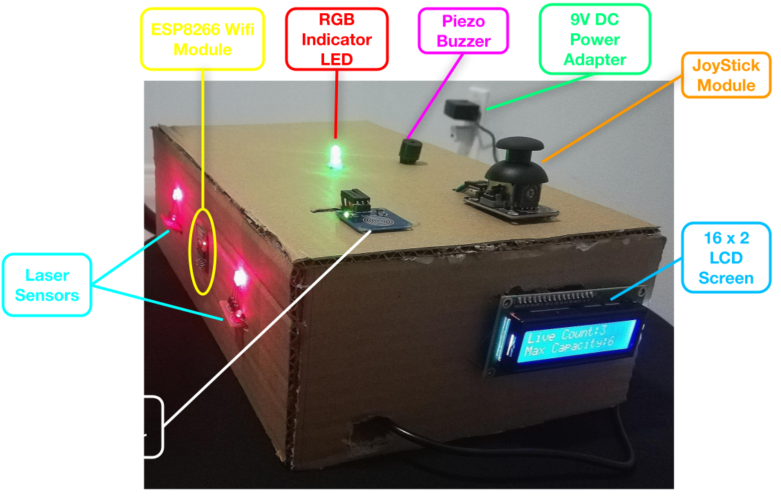
- Joystick: The joystick is used to increment and decrement numbers when setting up the count and capacity. It is also used to toggle through all the ASCII Characters when entering the Wifi Name and Password.
- Touch Sensor: The touch sensor is used during the device setup process.
- Piezo Buzzer: The piezo buzzer creates a quick beeping sound whenever the user presses the touch sensor. It also produces a constant beeping sound whenever the Live count goes over the max capacity to alert the user to walk back.
- RGB Indicator LED: During the laser setup, the RGB Led shows red when lasers are not pointing at the laser sensors, and it shows green when both lasers are correctly set up. It also turns red if max capacity is reached or exceeded, and it stays green for the rest of the time.
- LCD Screen: This displays all the instructions during the setup process. After the setup is complete, it shows the live count and capacity.
- Laser Sensors: The laser sensors return a value of 1 when the lasers are pointing at them and 0 otherwise. This information can be used to track if a person is going in or out of the area.
- Wifi Module: The ESP8266 wifi module can connect to the local wifi network and send data to a website.
- 9V DC Adapter: Powers the arduino, alternatives like a battery snap can also be used.
Laser Device
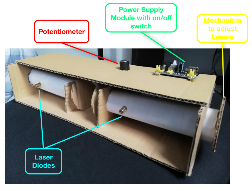
- Laser Diodes: Laser diodes emit a concentrated beam of light.
- Power Supply Module: This module comes with a built-in switch that allows it to be turned on/off. It is powered by a 9V battery, but it outputs a consistent power supply of 5V.
- Potentiometer: The potentiometer is a variable resistor that allows the user to control the brightness of the lasers.
- Laser Adjusting Mechanism: This mechanism can be rotated, which changes the angle at which the lasers are pointing, and hence changes the height of where the lasers point. It can also be shifted horizontally and allows the user to align the lasers with the sensors.
How this Device Works - Software
The software on this device can be split into three main categories -
- Wifi and Device Setup
- Person Tracking Algorithm
- Uploading Data to my Website
Wifi and Device Setup
Device Setup
The device setup code mostly involves receiving input from the joystick and the touch sensor, and then displaying some corresponding data on the LCD. Also, the piezo buzzer and the LED complement user input by providing feedback based on user input. For example, the piezo beeps whenever the user presses the touch sensor and the LED switches between red and green depending on the setup stage.
Wifi Setup
Typing using Joystick
Moving the joystick vertically toggles between ASCII characters, including common symbols, numbers, lowercase letters and uppercase letters. Moving the joystick horizontally changes cursor location.
Saving Wifi Credentials to Arduino's EEPROM
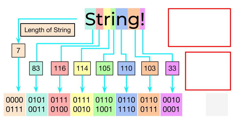 Arduino’s EEPROM is 1 kb, which means 1024 bytes. Each byte is given a memory address from 0-1023. Each of these memory addresses can store an 8-bit binary value.
Memory address 0 is used to store the length of the wifi name string. Then, each character in the string is converted to an integer value using ASCII and those values are converted to binary. Each binary value is stored at a memory address.
The password string is stored in the same way, except, instead of starting from 0, the string is saved starting with the next available memory location.
Storing the length of the string before storing the actual string is important because the length of the string tells the read function how many memory addresses to read to get the full string.
Person Tracking Algorithm
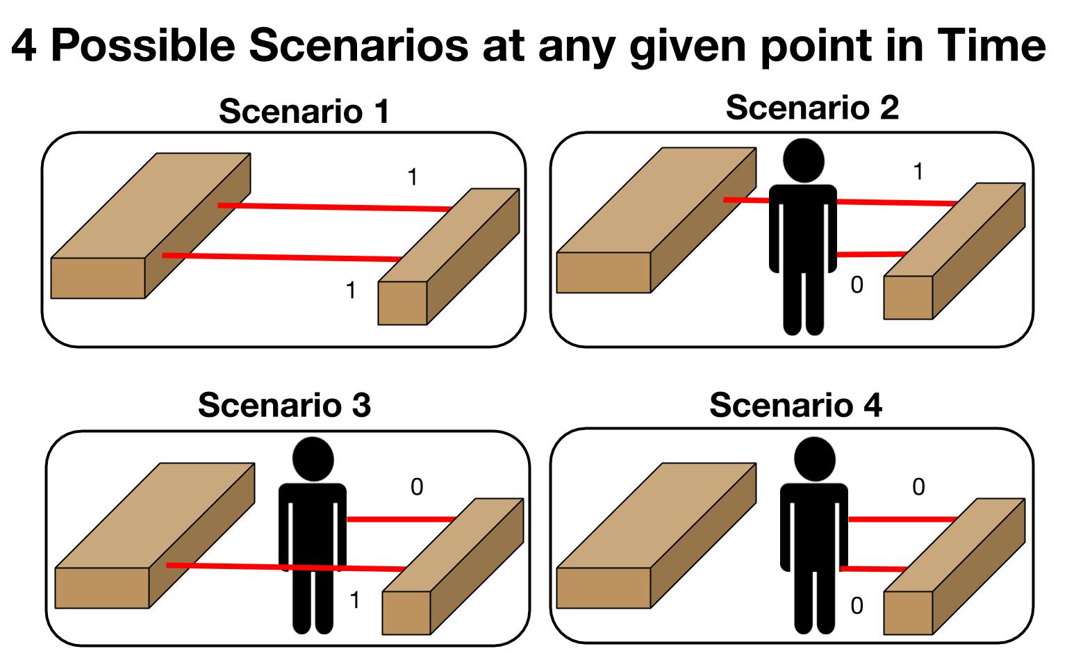
The people tracking algorithm is designed in a way so that it can handle normal cases as well as edge cases.
At a given point in time, the device can be in any of the four states shown in the diagram - Either both laser wires are connected, or one of them is tripped or both of them are tripped.
-
This algorithm records two pieces of data -
- The laser wire that was first blocked, which would give the initial direction from where the person came.
- The laser wire that was last unblocked, which would give the final direction from where the person left.
A key assumption that must be made for this algorithm is that the lasers are close enough to each other that no one can stand in between them without blocking at least one of them. Hence, the lasers are placed very close together on the device.
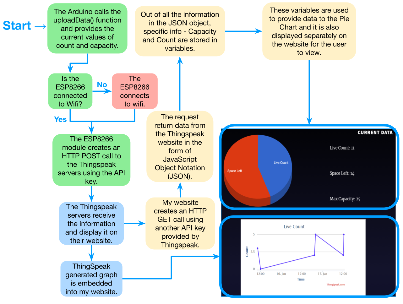
Uploading Data to my Website
The arduino uploads data to my website every 32.5 seconds. The process of how my code works to achieve this can be seen in the flowchart diagram.
Design and Reflection Report
- Adhiraj Singh
- HTML 5